
A vehicle may produce warmer-than-expected vent air, unstable cooling, and gauge readings that do not match a familiar pattern. Those observations can arise when compressor output is restricted, when refrigerant delivery to the evaporator is incorrect, or when neither valve is at fault. The useful starting point is to separate two jobs: controlling how much refrigerant the compressor pumps and controlling how much refrigerant enters the evaporator.
Identify the system before interpreting its behavior
A compressor control valve is mainly associated with a variable-displacement compressor, meaning one whose pumping capacity can change without requiring the shaft to stop. An externally controlled valve receives an electrical command from the vehicle’s control system. An internally regulated valve responds to pressure conditions within the compressor. The applicable arrangement, command strategy, and test method depend on the compressor and vehicle design.
Not every system has this type of capacity control. A fixed-displacement compressor may regulate operation through cycling or another vehicle-specific strategy, while an electric compressor commonly changes output through controlled motor speed. Its internal construction and control logic still must be confirmed from service information. Consequently, a test or pressure interpretation developed for one architecture should not automatically be transferred to another.
The compressor control valve changes pumping capacity
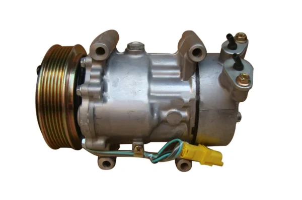
In a common variable-displacement swash-plate compressor, pistons are driven by an angled plate. Changing that angle changes piston stroke and therefore the volume of refrigerant moved per revolution. The control valve influences the pressure balance inside the compressor, allowing the swash-plate angle and displacement to vary. It does not directly meter the liquid refrigerant entering the evaporator.
This explains why a turning pulley, rotating shaft, or engaged clutch does not prove full pumping capacity. The compressor may be operating at reduced displacement because the control system is limiting output, because its control valve is not responding correctly, or because another condition is affecting compressor operation. On an externally controlled system, an electrical command also does not by itself prove that the compressor achieved the requested mechanical output.
Conversely, low indicated output is not automatically a valve failure. The controller may deliberately reduce displacement in response to evaporator temperature, pressure, thermal load, or another documented operating condition. Diagnosis therefore requires both the commanded state and the system’s actual response.
The expansion device controls evaporator refrigerant delivery
The expansion device creates the pressure drop needed for refrigerant to enter the evaporator at a lower pressure and temperature. On a system with a thermostatic expansion valve, often abbreviated TXV, the valve modulates flow to regulate evaporator outlet superheat. Superheat is the amount by which refrigerant vapor temperature exceeds its saturation temperature at the corresponding pressure. It indicates whether refrigerant leaving the evaporator has fully vaporized, rather than serving as a direct measure of vent cooling.
A typical TXV uses evaporator outlet temperature sensing together with pressure equalization to position the valve. Restriction, sensing problems, contamination, or incorrect operating conditions can disturb that balance. However, the same description cannot be applied to every system. A fixed-orifice arrangement has no actively modulating superheat-control valve, and an electronically controlled expansion valve depends on sensors, controller decisions, and valve actuation.
Incorrect evaporator metering can reduce heat absorption or make cooling unstable, but the resulting pressures depend on compressor response, refrigerant charge, heat load, airflow, and the control strategy. There is no universal high-side and low-side gauge combination that isolates an expansion valve across these architectures.
Why the symptoms overlap during diagnosis
Reduced compressor displacement and abnormal evaporator metering can both leave the evaporator unable to absorb enough heat for the current load, commonly raising vent temperature. Yet restricted refrigerant charge, poor condenser or evaporator heat transfer, incorrect sensor inputs, electrical faults, and air-distribution problems can produce similar complaints. A blower or blend-door fault can also make vent performance poor even when the refrigerant circuit is operating correctly.
Gauge pressures describe the circuit at particular test ports and operating conditions; they do not identify a failed part on their own. Condenser airflow, ambient temperature, heat load, compressor commands, and expansion-device behavior all influence them. Front-mounted condensers normally receive outside air first, but hot-air recirculation, fan problems, obstruction, or other vehicle-specific conditions can alter heat rejection. Likewise, subcooling and pressure changes must be interpreted according to system design rather than treated as fixed signatures.
A disciplined diagnosis records ambient and operating conditions, verifies fan and air-side operation, compares line and vent temperatures with gauge readings, and checks available command and sensor data. Vehicle service information should establish the intended control strategy, valid test states, and acceptable values. Weak cooling or an unusual pressure reading may justify further testing of either valve, but it does not by itself justify replacing one.
Product image from COOLMASTER · 配图仅作产品类别示意,不代表具体车型适配建议