A blower that sounds weak, works intermittently, or loses only certain speed settings can produce the same customer complaint: insufficient airflow at the vents. Those symptoms do not identify a failed motor by themselves. The motor and its speed controller perform different jobs, and restrictions in the air path can make either one appear faulty. A useful diagnosis therefore separates three questions: Is the motor receiving the intended electrical power, can it convert that power into blower-wheel speed, and can the resulting airflow reach the cabin outlets?
The motor moves air; the controller regulates its operation
The blower motor converts electrical power into shaft rotation, driving the blower wheel inside the HVAC housing. Airflow depends on more than the motor itself. Wheel condition, housing clearances, inlet restrictions, and resistance through the evaporator, heater core area, ducts, and outlets all affect how much air is delivered.
The speed controller regulates motor operation. This is a functional description, not a single component design. On a traditional system, the controller may be a resistor pack with several resistive elements. On an electronically controlled system, it may be a power module containing solid-state switching devices. Switches, relays, climate-control electronics, wiring, fuses, and grounds can also form part of the control path.
This division of labor provides an important diagnostic boundary. A motor can be mechanically sound but run slowly because its supply voltage is inadequate. Conversely, a controller can provide the expected electrical output while airflow remains poor because the wheel is obstructed, the motor is worn, or the downstream air path is restricted.
Resistor packs and electronic modules require different interpretations
In a conventional resistor-controlled circuit, selected resistive elements reduce the voltage available to the motor at lower speed settings. Electrical energy dissipated by the resistor becomes heat, which is why these assemblies are commonly positioned where blower airflow can cool them. Many designs provide a higher-speed path that bypasses some or all of the resistance, but the exact arrangement varies.
On such a vehicle, losing one or several lower settings while another setting still works can point toward a particular resistive branch, its connections, or associated protection. It is a clue, not a universal signature. A wiring diagram must establish how the speeds are routed before that pattern is used as evidence.
An electronic power module commonly regulates motor power through solid-state switching. Some designs use pulse-width modulation, meaning the power is switched rapidly to control the average power delivered. The module may receive commands from a manual control panel or climate-control electronics, and the command method is design-dependent. A test suitable for a simple resistor circuit may therefore give misleading results on a module-controlled circuit; in particular, an ordinary meter reading of a pulsed output may not represent motor power accurately.
Why speed-selection symptoms often overlap
Uniformly weak airflow at every requested speed does not automatically implicate either the motor or the controller. A restricted cabin-air filter or inlet can reduce airflow while the motor operates normally. Debris on the blower wheel, a wheel that is not secure on its shaft, excessive mechanical loading, or internal motor wear can also reduce output. Evaporator contamination or icing can add downstream resistance, although the cause of any icing requires a separate diagnosis.
Air delivery and blower speed should also be distinguished. If the motor sound changes normally with the settings but little air leaves the selected vents, a mode-door, duct, or distribution problem deserves consideration. Door operation varies by system and should not be inferred from motor noise alone.
Intermittent operation adds further overlap. Loose connections, heat-damaged terminals, excessive circuit resistance, motor condition, and module behavior can all interrupt operation. Likewise, complete loss of selected speeds is more suggestive of a control-path fault than uniformly low airflow, but neither pattern is conclusive without knowing the vehicle’s circuit architecture.
Use loaded measurements and air-path inspection to separate the causes
Start by recording the requested settings, blower sound, actual vent delivery, and whether the complaint changes with operating time or vehicle movement. Inspect the accessible inlet, cabin filter, blower wheel, and visible air path. Where service information provides live data, compare the requested blower command with the reported output or status, remembering that a command signal does not prove that the power stage or motor is functioning.
Electrical checks are most informative with the circuit operating under load. Using the applicable wiring diagram and terminal identification, check available supply, ground integrity, and voltage drop across the relevant connections. Excessive drop on the supply or ground side can leave the motor underpowered even when an unloaded voltage reading appears normal. On resistor systems, interpret output voltage according to the selected resistive path. On electronic systems, follow the specified test method rather than assuming a steady DC output.
Motor current and mechanical drag can provide additional evidence, but acceptable limits and test procedures must come from vehicle or component service information. Applying direct power may be useful only where the manufacturer provides a suitable procedure; it does not by itself clear the air path or quantify motor condition.
The strongest conclusion comes from agreement among the circuit measurements, command information, motor response, and physical inspection. Replacing a resistor pack because one speed is missing, or a motor because airflow is weak at every setting, goes beyond what either symptom alone can establish.
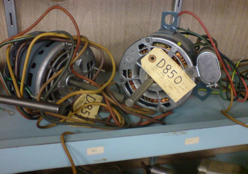
blower motors and wires by Inha Leex Hale · Flickr · CC BY 2.0 · Resized for display; illustrative photo, no endorsement implied.